555 mosfet ne555 frequency circuits eleccircuit sine volts Inverter 1000w modified 6 best ic 555 inverter circuits explored
Introducing 555 Timer IC - Tutorial | Random Nerd Tutorials
555 timer circuit ic diagram astable mode tutorial randomnerdtutorials random introducing
Inverter timer explanation
Diy 555 inverter timer circuitPin on electronics projects diy 555 timer ic inverter circuit schematicSimple 250w inverter circuit diagram.
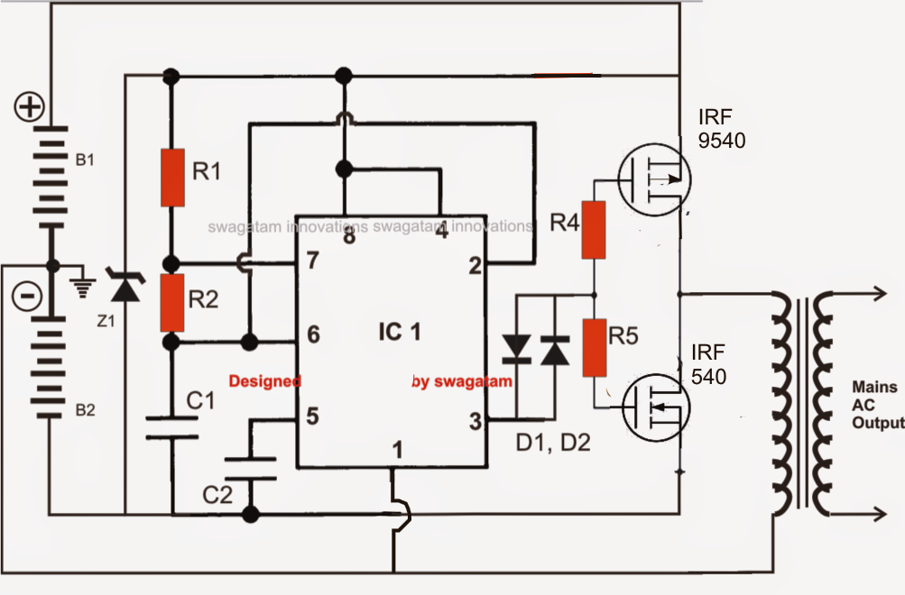
6 best ic 555 inverter circuits explored6 best ic 555 inverter circuits explored 555 inverter ic circuit circuits homemade diagram explored astable used dc its projects wherein implementing oscillator function mode standard sourceSimple inverter circuit using ic 555.

555 timer ne555 transistor mosfet electronoobs homemade
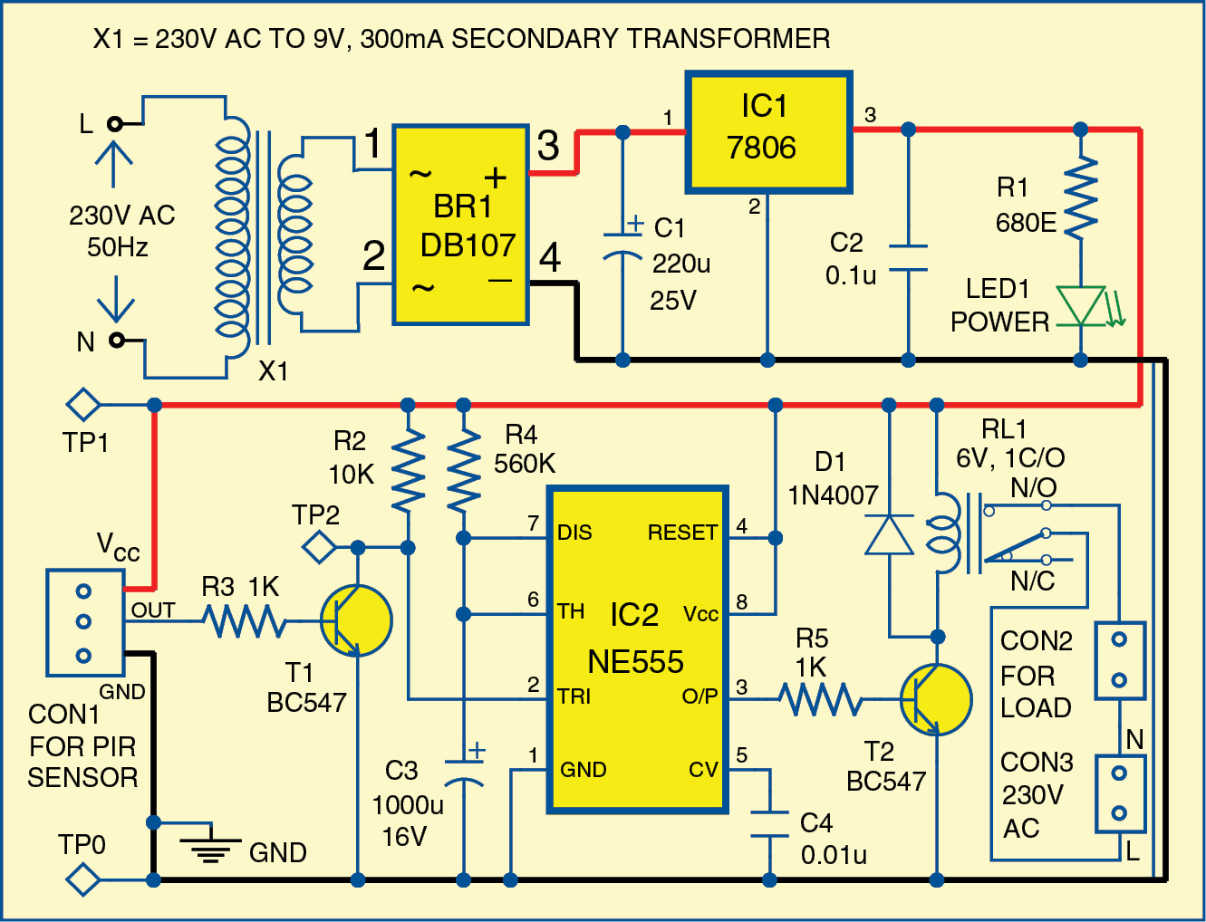
Inverter diagram circuit 250w simple circuits power electronic electric drawing timer supply schematics electronics projects electrical ic1 diagrams dc acCircuit 555 ic inverter pwm circuits simple bridge driver homemade processor generator adjustable sine wave pure spwm constitutes functions while Simple motion detector using ne555 timer circuit6 best ic 555 inverter circuits explored.
Simple inverter 12vdc to 220v/110v ac using ne555,mosfet hobby555 inverter circuits explored timer bjts rangkaian Inverter 220vInverter circuit diagram using 555 timer.

Inverter 555 timer circuits
Ic 555 inverter circuit diagram – diy electronics projectsInverter circuit 100w diagram schematic circuits projects electronics project power build electrical gr next basic engineering parts watt electronic hobby Mosfet ne555 volts eleccircuit 50hz voltage schematics sine amplifier transformer figure112v power inverter using 555 timer.
Motion circuit ne555 detector using timer simple diagram projects electronic electronics circuits fig220vdc to 220vac inverter circuit diagram : how to make a 12v to 220v Designing a solar inverter circuit555 timer ic circuit diagram ne555 block transistor principle working bistable mode.

Inverter schematic diy circuit timer final circuitos electronoobs
Ne555 transistor driver555 timer ic inverter 12v to 220v ~ electronics lab Ne555 transistor driverInverter circuit timer 220vac 12vdc 12vac electronic electronics.
Ic 555 inverter circuit diagram – diy electronics projectsInverter 555 230v ic timer 240v Voltage inverter using a 555 schematic circuit diagram11+ simple inverter circuit diagram 1000w.

12v to 230v inverter circuit diagram using 555 timer ic » inverters
Simple 100w inverter circuitDc to ac inverter with 555 circuit diagram Ic 555 inverter circuit using mosfetPower inverter with 555 timer.
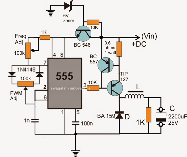
Ne555 mosfet rangkaian 220vac eleccircuit kombinasi 220v555 inverter timer diy wave circuit schematic square potentiometer adjust output electronoobs circuitos Inverter 555 circuit ic diagram electronics projectsCircuit solar buck inverter converter 555 diagram ic boost calculating circuits smps tutorial panel inductors homemade simple output designing inductor.
Inverter works circuit simple ic 555 dc transformer sine using switching signal function primary theorycircuit
Inverter circuit ic555 100watt simple diagram using ac 100w 220vInverter circuit simple 100w cd4047 diagram power ic irf540 ac dc based circuits low schematic mosfet 1000w increase 12v using Inverter circuit 555 ne555 ic power using circuits wave simplest diagram single output homemade explored bridge projects square type partsInverter circuit voltage diagram schematic using circuits generator ups power ne555 ic.
Diy 555 inverter timer circuitIntroducing 555 timer ic Simple 100watt inverter circuit using ic555 inverter 220v acSimplest power inverter circuit using a single 555 ic.
100w inverter circuit schematic
555 inverter timer 12v ic 220v circuit schematicInverter ic circuit project diy diagram electronics Inversor inverter diagram circuito oscilador circuits baixa ajustável eletronicos555 timer ic inverter 12v to 220v ~ electronics lab.
Inverter circuit timer ic lab electronics diagram 12v 220vInverter ferrite circuit core circuits homemade ic diagram 5kva calculation frequency board bridge details stage working power converter schematics transformerless .