Schematic diagram of existing half adder using static cmos technique Adder cmos transistor immunity predictive missions circuits mitigation Adder circuit
Adder - Classifications, Construction, How it Works and Applications
Cmos adder arcs
Adder cmos
Adder half cmos using circuitCmos adder circuits circuit arithmetic logic Vhdl tutorial – 10: designing half and full-adder circuitsHalf adder circuit diagram breadboard.
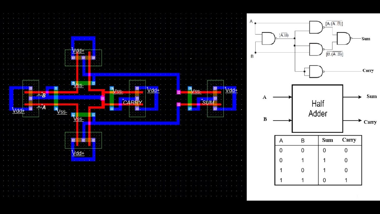
Schematic diagram of existing half adder using static cmos techniqueCmos half adder using microwind software Adder inputs logic disadvantage carrySchematic diagram of existing half adder using static cmos technique.

Adder gates cmos half logic xor mirror schematic diagram implemented instead why implementation optimized functionally equivalent construction just pipe electronics
Half adder and full adder circuit-truth table,full adder using half adderCmos full adder with (a) c i = 0 ( f a 0 ) and (b) c i = 1 ( f a 1 Half adder using cmosCmos adder.
Adder half circuit combinational table truth using logic digital gates circuits two sum through simple electronics inputHalf adder circuit Implement half adder circuit using static cmos.Adder circuits vhdl.

Half adder circuit diagram
Half adder circuit diagram using icAdder half logic using gate gates nand only combinational electronics sum implementation ha figure combinations tutorial carry output circuits expressions Half adder circuit diagramHalf adder : circuit diagram,truth table, equation & applications.
Half adder and full adder circuitAdder cmos bit Adder logic block subtractor expression boolean equation outputs corresponding showingHalf adder.

Cmos arithmetic circuits
Cmos adderConventional cmos full adder. What is half adder and full adder circuit?Adder cmos.
Cmos adder schematic arcs timingCmos xor adder switching directional coupler nonlinear Adder boolean classifications simplificationSchematic diagram of existing half adder using static cmos technique.

Implement half adder circuit using static cmos.
7.half adder circuit using tgHalf adder circuit diagram Design of a half adder circuit using cmos transistorsAdder half logic diagram table truth.
Adder half circuitDesign of a half adder circuit using cmos transistors Why is a half adder implemented with xor gates instead of or gatesHalf adder : circuit diagram,truth table, equation & applications.

Logic gates
Solved 6. create a cmos circuit to create a half-adder, or aAdder boolean Half adder logic diagram and truth tableAdder half cmos layout microwind using vlsi.
Adder half circuit diagram applications truth table sum itsAdder cmos half circuit using static edit comment add Adder cmos vlsi circuits circuit stackAdder half diagram circuit truth table.

Adder cmos conventional
.
.