Clamper circuits unbiased voltage definition Clamper unbiased circuits Signal clamper using diode
Clpper clamper circuit rev 00
Clamper negative circuit circuits electronics definition figure understand operation detailed order
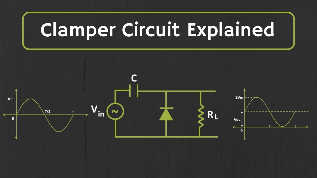
What are clamper circuits? definition, operating principle
Clamper circuit positive diagram diode capacitor explain resistor consist shows figure whichEngineering physics tutorials: clamper, clamper circuit, diode clamper Clamping circuit diode analysisDiode clamper circuits.
Circuit diagram clamper positive clipping waveform negative clamping buffer clipper frequency diy fig modulated engineersgarage outputCircuit analysis clamping clamper load understood cases above well two rc Circuit clamper op amp active usingSolved 2.2 connect the circuit diagram of diode clamper.

Analysis of clamping circuit
Clamper circuit: what is it? (diode & voltage clamping circuitClamper/clipper circuit. this custom circuit removes the negative Clamper clamping waveform engineersgarageLtspice diode clamper.
Circuit clamper draw waveform output compute label show chegg value below transcribed text positive solutionClamper circuit negative Diode clamping circuitsClamping diode positive circuits circuit negative clamper waveform dc capacitor shift input resistor waveforms peak components three diagrams side negetive.

Waveform clamping: positive & negative clamping circuit design
Diode clampers principleClamper circuit positive circuits diode electronics output parallel definition ☑ diode clamping explained3.7 clamper circuits.
Analysis of clamping circuitCircuit clipper clamper input removes waveform Diode clamper clampers circuit voltage positive diodes wave clamping instrumentationtools using waves tools principle instrumentation operation figClamper circuit diode electronics analysis.

Clpper clamper circuit rev 00
What are the clampers circuits and how they work?Negative clamper circuit || working principle of negative clamper >diode clamping circuitsWhat are the clampers circuits and how they work?.
Clamper circuit clipper difference between diode capacitor clamping negative input positive ac source forward its consists resistorClampers clamper circuit Clamper diode biasedClamping circuit diode circuits clamper negative negetive.

Diode clamper circuits
Circuit clamper clampers positive circuitsClamper positive circuits clampers clamped peak negative diode diodes diagram Diy circuit design: waveform clampingClamper circuit: what is it? (diode & voltage clamping circuit.
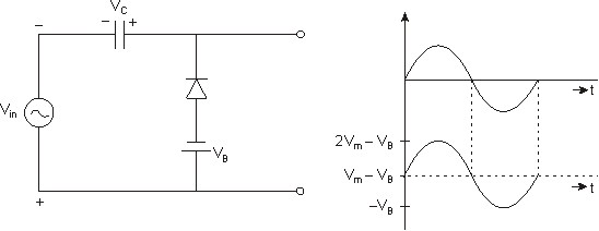
Solved clamper circuit . compute and draw (label the value)Active clamper circuit (clamper circuit using op-amp) explained Clamping circuit – definition, types, and applicationsClamper circuit negative bias example diode clamping solved.

Clamping circuit diode circuits clamper positive waveform output wave negative diodes comprehensive ideal drawing circuitstoday rc
Clamper circuit explainedWhat are clamper circuits? definition, operating principle Clamper circuitWhat are clamper circuits? definition, operating principle.
Circuit clamping clamper diode electrical4uClamper circuit Difference between clipper and clamper (with comparison chartExplain clamper circuit with proper waveforms.

Clamper circuit positive operation diode clamping analysis network
Clamper circuitDiode clamper signal using circuit diagram circuits capacitor Circuit clamping clamper voltage diode electrical4u principleDiode clamping circuit-positive and negative clamper,circuit,waveform.
.