Rectifier circuit diagram Wave rectifier half circuit diagram positive current working sine alternation figure Rectifier wave circuit capacitor theory load working rl calculate diagram bridge half output dc types physics
Full-Wave Rectifier Circuit - Inst Tools
Precision full wave rectifier circuit diagram
Rectifier bridge wave capacitor filter diagram circuit formula schematic voltage diode calculation output shocks electric diodes choose board operation
Full wave rectifier-bridge rectifier-circuit diagram with design & theoryRectifier circuit diagram Rectifier bridge wave circuit diagram diode voltage peak operation fig inverse value secondary its negative shown belowFull wave rectifier circuit diagram (center tapped & bridge rectifier).
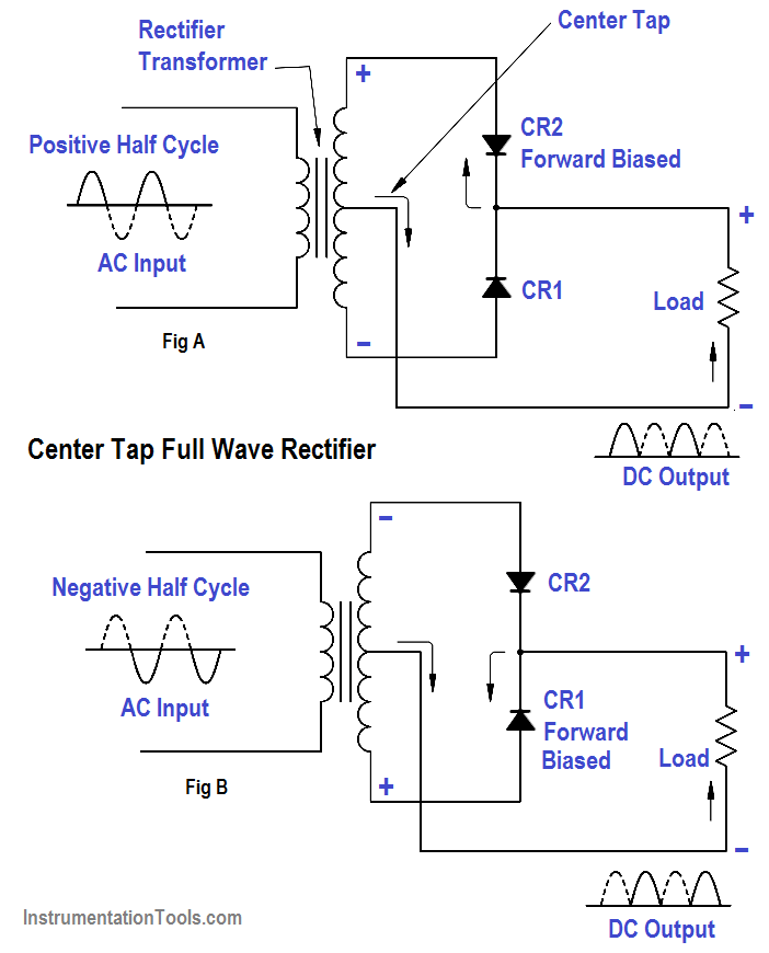
Rectifier bridge wave capacitor filter circuit diagram diode half rectifiers rectification transformer using diodes keywords trending gates logic fourRectifier wave circuit tap center half Dictionary of electronic and engineering terms, full-wave rectifier circuitRectifier bridge wave circuit diagram capacitor filter prototypes application.

Half wave & full wave rectifier: working principle, circuit diagram
An introduction to rectifier circuitsDraw the circuit of a full wave rectifier using two p-n junction diodes Wave rectifier circuit centre tap tapped electronics representation shows below figureBridge rectifier : circuit diagram, types, working & its applications.
Full wave rectifier circuit working and theoryHalf & full wave rectifier Rectifier block diagramRectifier wave bridge circuit operation contents its disadvantages advantages.

Half and full wave rectifier working principle
Center tapped full wave rectifier : circuit and applicationsRectifier circuit bridge working diagram operation theory ac supply 12v transformer circuits step down electrical types use Three-phase rectifier circuit.Full wave rectifier : circuit diagram, types, working & its applications.
Rectifier wave circuit tapped bridge diode diagram center capacitor filter theory voltage diodes dc fullwave electronics half transformer power loadCircuit diagram of full wave rectifier with capacitor filter Rectifier cbse diodesFull wave bridge rectifier.

Rectifier diode waveform
Rectifier wave circuit precision diagram simple ac dc gr circuitsstream circuits sourced next super schematic diagramsRectifier circuit principle Rectifier circuit circuits articles figure introduction allaboutcircuitsCircuit diagram of full wave rectifier with capacitor filter.
Rectifier circuitstoday tapped multisimCenter tapped full wave rectifier Full-wave rectifierFull wave bridge rectifier circuit working and applications.

Full wave bridge rectifier
Build a full wave rectifier circuit diagramRectifier diagram bridge circuit wiring wave applications Full wave bridge rectifier circuit diagramRectifier circuit diagram output waveform input.
What is half wave and full wave rectifier?Full-wave rectifier circuit with resistive load. Rectifier transformer tapped waveform etechnogSingle phase half wave rectifier- circuit diagram,theory & applications.

Rectifier tapped transformer diodes diode equations
Full wave bridge rectifier with capacitor filter design calculation andRectifier resistive menghitung kebutuhan cara Rectifier wave half circuit diagram diode rectification ac crystal operation used supply rectified connected shown below throughRectifier wave circuit filter without diagram bridge capacitor tapped diodes center circuits below board four using circuitdigest added when type.
Full-wave rectifier circuitFull wave rectifier circuit diagram in multisim Rectifier wave diagram circuit working theoryRectifier wave tapped center circuit diagram its contents operation.

Zener bridge rectifier circuit diagram
Zener circuit bridge diagram rectifier diode wiring diagramzFull wave diagram What are full-wave rectifiers? definition, centre-tap full-wave.
.