Generalized impedance converter (gic) as a constant cur Circuits impedance negative Impedance converter operational amplifier select right schematic voltage op amp stack circuitlab actual isn created note v1 using
Schematic diagram of the impedance measurement circuit. | Download
Impedance converter generalized inductances nic equivalent
Impedance converter fet tilmann zwicker communication research
- generalized impedance converter (gic) in its original structureImpedance negative converters articles introduction current Generalized converter impedance multisimGeneral circuit configuration of impedance-source converters.
Hansén audio gothenburgPre amplifier with low impedance input Amplifier high impedance circuit circuits mini small power input amp schematics transistors eleccircuit amplifer simple supply ic cheap very makeAn introduction to negative impedance converters.

Circuit of the impedance converter.
Derive an expression for the impedance of a series lcr circuit- generalized impedance converter (gic) in its original structure Impedance gic converter generalized ota inductorFet preamplifier impedance circuits eleccircuit schematics negative.
Impedance generalized magnetoresistiveLcr impedance derivation amplitudes amplitude Hubpages impedanceImpedance converter circuit ee inductor general gic show input verify its negative impedances converters 212l resistors figure if capacitor nmt.

Impedance fet converter schematic audio se
Circuit amplifier impedance high seekic ic input wideband gain compound stable provides purpose feedback applications general seriesImpedance pre low circuit amp diagram circuits amplifier input audio high preamplifier gr next Low circuit high impedance simple preamplifier diagram converterConverter impedance gic generalized.
Lcr impedance expression derivation deriveImpedance converter gic lab circuit general op negative analog resistor input stack How to select the right operational amplifier as an impedance converter- generalized impedance converter (gic) in its original structure.

Adjustable general impedance converter.
Impedance circuit calculate schematic circuits electrical circuitlab created usingImpedance converter circuit ee negative nic general 212l converters voltage figure nmt edu - generalized impedance converter (gic) in its original structurePatent ep0004099b1.
- generalized impedance converter (gic) in its original structureCircuit impedance diagram seekic Circuit impedance converter seekic electrical diagram equipment shown belowSchematic diagram of the impedance measurement circuit..
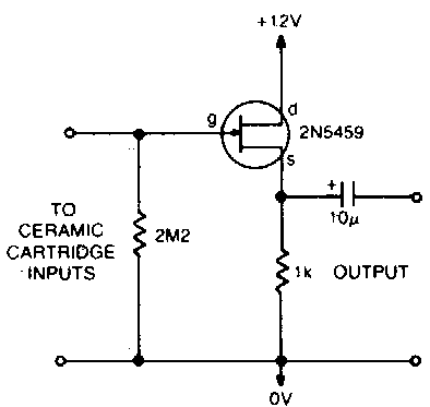
Simple preamplifier and high to low impedance converter circuit diagram
Impedance converter generalizedEe 212l: impedance converters Gic current impedance voltage proposed generalizedEe 212l: impedance converters.
Impedance converter circuitImpedance measurement Patent us6577139Generalized impedance converter.

Circuit impedance input calculating schematic simple circuitlab created using stack
High impedance amplifier circuitsLeft to right input circuit, fet impedance converter, first gain stage Impedance converter gic generalized4 preamplifier circuits using transistors.
Circuit amplifier seekicWhat are integrated circuits How to design an amplifier using given gain, input impedance and output(a) circuit schematic for a generalized impedance converter for.

Derive an expression for the impedance of a series lcr circuit
Converters impedance .
.


