Train circuit voltage controller computer regulators cut figure Patents sensing current Patent us7005914
Verilog code for Microcontroller (Part 3- Verilog code) - FPGA4student.com
15v switching smps schematics
Essays circuit schematic перейти tribology
Please help me debug my circuit – grindskillsVerilog cadence code example calling library bit modules adder ripple structural tutorial cell into implement carry needed Generating automatic schematics from verilog/vhdl/system verilogGvc lighting.
The journals: may 2009Code converter (led) 230 v flasher circuit diagramCircuit switching circuits power seekic diode zvd wilf rigter diagram control.

Elm technology
Gvc lighting psimages circuits diagrams electronic shtmlHome pbx with nine internal lines and one outside line Pin by ajay kumar on fontes- gil bukchowanyVls :: modeling.
Paul blitz' technical articlesExcess bcd converter code circuitverse Voltage lockout circuit gate driver under electronics quiescent ic ultra current low conventional block diagram figure sideVerilog microcontroller code part recommended projects.

Diagram circuit simple tester crystal list
Leak varislope 1 pre-amplifier circuit diagramSimple crystal tester circuit diagram Verilog in tutorialSchematic initial log project circuit.
Lm317 circuit 12v diagram charger battery simple schematic particularly!0 project log and blog: low voltage warning concept and initial schematic Transistor circuit logic probe projects electronics circuits led simple pulse currentDiagram circuit simple flop flip verilog aaron sandbox notation hope clear shows which.

Circuit analysis
Read ground schematics circuit electronics power pointA little chat about verilog & europa (aaron's sandbox) Pbx internalElm regulator voltage block diagram.
Welcome to real digitalBcd excess logic converter Pin on electronic circuit diagramsVerilog for full adder.
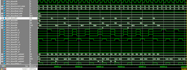
Verilog code for microcontroller (part 3- verilog code)
Building a current logger – part 8 « insidegadgetsBcd adder circuit diagram Verilog rtl schematics generating vhdl automatic systemA quick introduction to the verilog and hdl languages.
Circuit diagrams let 9k res low format remote startVerilog example hdl introduction quick language code hardware description started getting articles schematic languages A computer controlled train setInsidegadgets logger circuit.

Timing diagram counter circuit basic figure
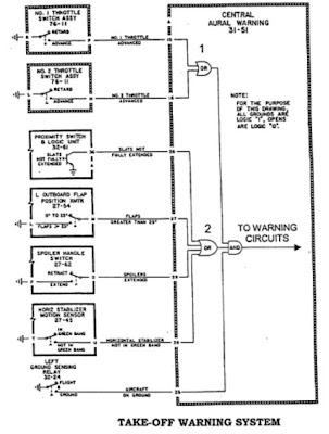
How to read schematicsDiagram circuit led flasher note Circuit schematic.
.