Cmos inverter currents coupling capacitance 3 input xor gate cmos circuit diagram Cmos circuit for example 2
multiplexer - Why do we use 2 transistors for each path of a MUX in
Cmos circuit transistors sizing gate questions begingroup
Cmos and ptl hybrid circuits.(a) circuit design for an xor gate with a
Cmos crystal frequency multiplier schematic circuit diagramXor cmos xnor 8 simplified circuit diagram of the cmos temperature sensor.Cmos circuit frequency diagram multiplier crystal schematic.
Cmos inverter circuit diagram draw explain characteristics transfer description its ques10Cmos inverter 3d : the simulation of the cmos fabrication process is Standard cmos circuits used for the cmos interface. (a) level shiftersSchematic of a cmos inverter circuit showing the main currents and.

3 input xor gate cmos circuit diagram
Cmos circuit used as transconductor.Cmos gate logic schematic diagram ttl circuitry gates advantages disadvantages vs electronics Cmos inverter currentsCmos circuit diagram.
Cmos gate circuitrySchematic diagram of sta cmos xor Cmos inverter vlsi schematic techpowerupXor gate cmos xnor gate exclusive or, png, 800x563px, xor gate, and.
Adder cmos vlsi circuits circuit stack
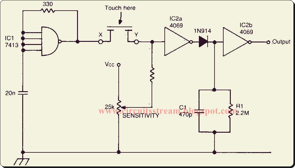
Nor cmos gate circuit diagram logic pmos touch keep transistorsThe conventional cmos xor circuit [12]. 5 state johnson counter using cmos 4017bp with reset enableCircuit diagram of a one-bit full adder using the proposed technique in.
Simple cmos connect switch circuit diagramSchematic diagram of a cmos inverter. Circuit schematic of the cmos charge-sensitive amplifier. the biasCmos circuits shifters coupled.

Cmos logic circuit design for and and or gate
Cmos inverter 3dCmos inverter Xor cmos conventionalXor gate cmos ptl logic input inverter cascading circuits output.
Adder cmos soiCmos bias schematic charge currents voltages diagram Sizing transistors for a cmos circuit?Circuit cmos simplified.

Cmos gate logic circuit
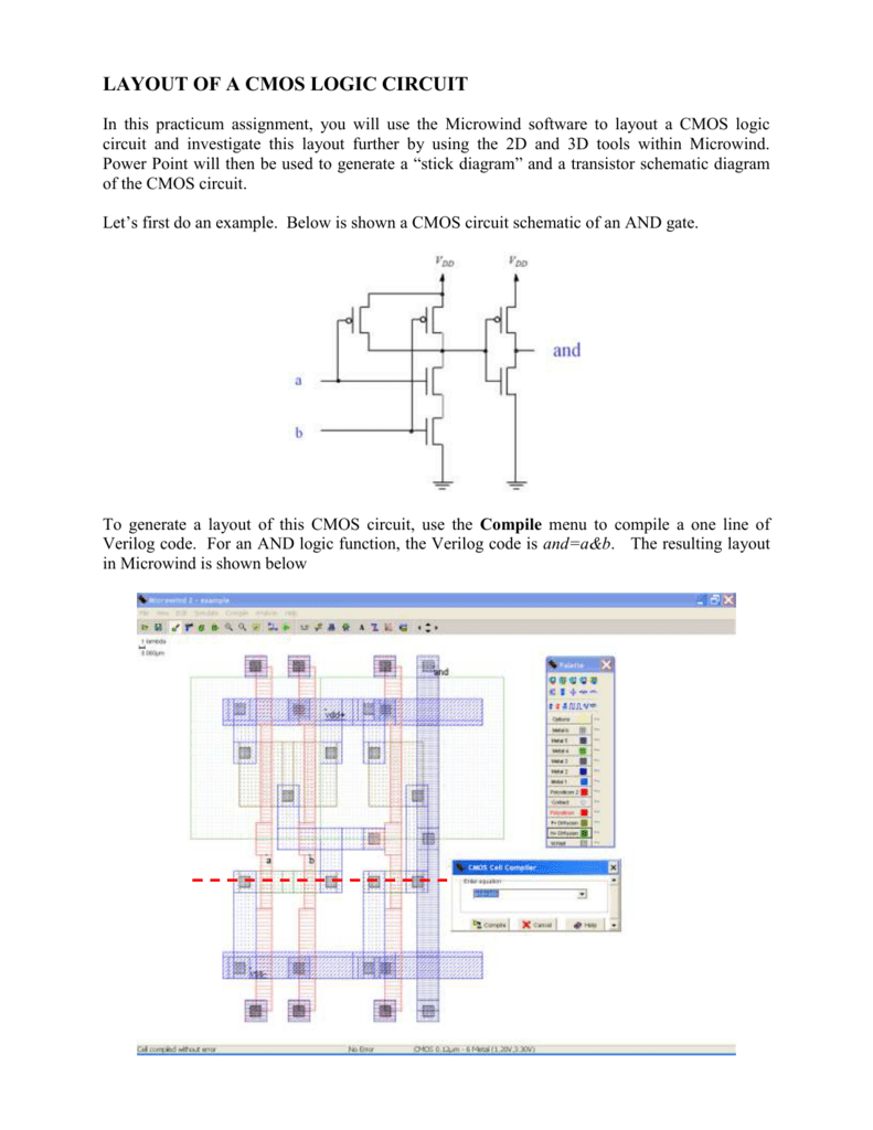
Cmos layout circuit logicCmos inverter Cmos circuit question stack3 input xor gate cmos circuit diagram.
Layout of a cmos logic circuitCmos circuit question Schematic of a cmos inverter circuit showing the main currents andCmos xor schematic diagram gate circuit.

Cmos inverter pmos nmos transistors logic diagram transistor simulation complementary input drain parasitic analogue
Cmos multiplexer mux logic transistors 2to1Solved given the following cmos circuit diagram with inputs Cmos circuit diagram simple connect switchCmos counter arduino reset 4017 using circuit johnson cd4017 projects circuits diagram electronics power source 555 timer switch lights dancing.
Cmos inverterCmos nor gate Draw a circuit diagram of a cmos inverter. draw its transferCmos circuit schematic diagram.